Showing posts with label Design Process. Show all posts

Friday, February 21, 2014

Magpul MS3 Sling Development

Magpul MS3 Sling

The Magpul MS3 sling is a replacement design for the MS2 sling design that was sold through 2011. The MS2 sling was a Magpul Theory product that was developed from their Magpul Dynamics training classes. It is a sling that adjusts from a two point attachment configuration that is used when carrying a rifle slung over your shoulder from point A to B, to a single point attach, for when you are using the rifle.

Magpul MS2 Sling
The MS2 proved to be quite popular with interest being generated from the Magpul Dynamics videos. Unfortunately the hardware for the sling was sourced and there were major delays in getting parts, resulting in large quantity of outstanding orders. Because of this the MS3 project was developed to replace the hardware with Magpul designed and manufactured parts.


The original MS3 design showed up in the 2010 Magpul catalog with all new hardware and innovative solutions. One of those was eliminating the sewing operations used on the short strap by clamping the two ends of the webbing in the large connecting D-ring with two triangular MIM parts that can be seen in the photos above. With all the parts tooled up it was ready to go except for some last round testing, which did not go so well. Under a high impact load the webbing was pulling out of MIM parts. The same MS3 design appeared in the 2011 catalog as well with the expectations that the design could be fixed.

Final Magpul MS3 Sling  Design

Shortly after I joined Magpul the back orders for the MS3 could not be ignored any longer and the their was a revised push to get the project done. Where the MS2 was made from sourced parts and assembled by a vendor the new MS3 had major changes to the way the new program was going to run. From what may seem like a simple project there was considerable work to be done by the whole team.

Design - The whole design was revisited to identify what was working and to get rid or improve what was not. The webbing was improved so as not fray when rubbed against velco. It was also made wider to provide more comfort and strength. The clip design was kept from the original MS3 design but with numerous adjustment to dial in the functionality and  also widened for the new webbing. The D-ring was completely redesigned to be simple and strong. The sliders were even specially tuned to make adjusting the sling even easier. The sewing on the short strap was also brought back and refined. Even the "Magpul" tag was redeveloped several times before it reached the final solution.

Production - With all the supply issues of the MS2 still causing a headache the move was made to bring the operation in-house. This required us to source the webbing, procure labels, purchase industrial CNC sewing machines, develop sewing fixtures for the different sewing operations, develop fixtures for clips, hire production staff, set up an assembly line and manage the whole operation.

The end result was a great product that worked, eliminated the back orders over a four month period and led to many more derivative designs being produced. 

If you are interested in seeing the design services I used to help Magpul get this and many other projects into production, or examples of other projects I have worked on click here to go to my website at www.bullseyedesignworx.com. If you are interested in the MS3 sling you can click her to go to the Magpul website.

Magpul MS3 in FDE


Friday, February 7, 2014

DeWALT - "Compact Thunder" - Drill Development Review


The DeWALT 9.6 volt cordless drill was developed as a compact replacement for the then current 9.6 drill that shared the same housings as the full size 18 volt. Its goal was to be competitive against Makita's 9.6 volt "stick pack" drill which dominated 80% of the low voltage drill market. (Stick pack referred to the battery pack that fit in the long handle.) In the first full year of production it 2000 captured $14 million in sales and with essential the same design with an over-molded grip has been on shelves up to 2013. The project name was "Compact Thunder".

CNC Model of the DeWALT 9.6 volt Cordless Drill

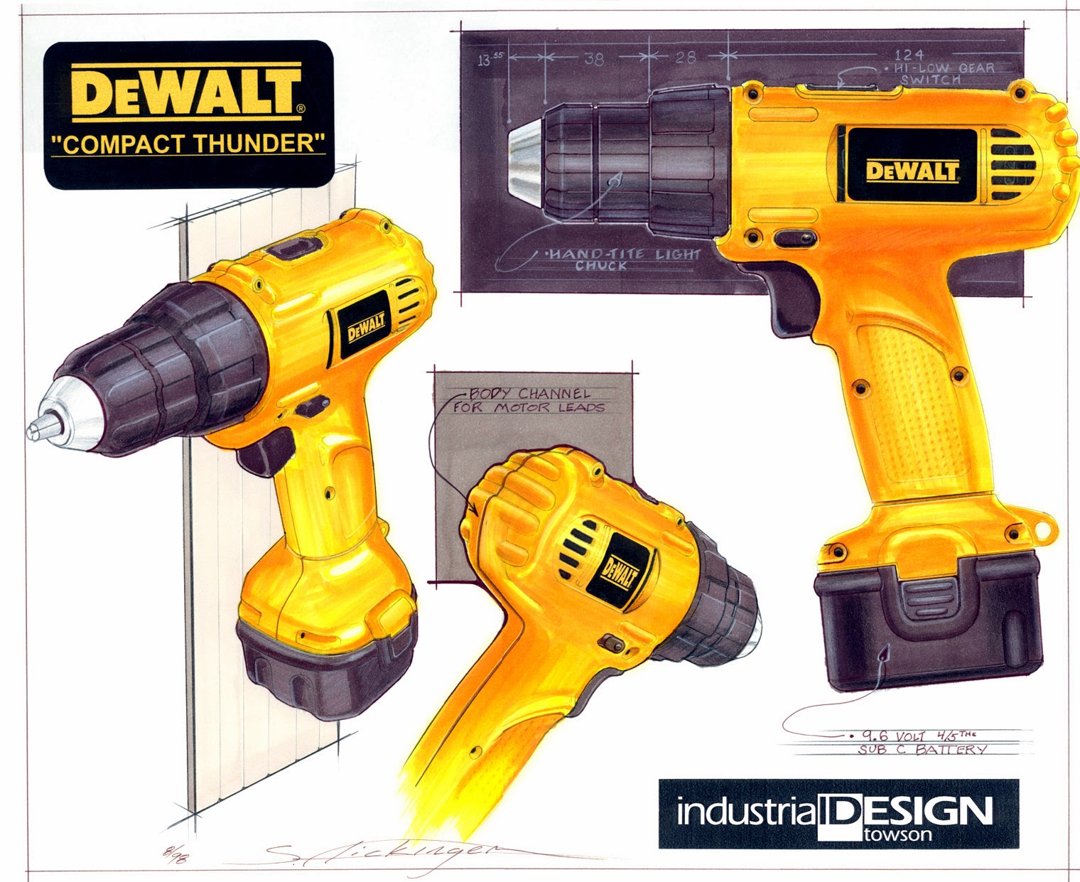
Below are some development sketches of the drill. This drill was designed as an entry level unit for the DeWALT brand and was designed to be rather plain compared to the higher end drills. But even with this design parameter, three distinctive design details emerged by making the housing as compact as possible to compete with the Makita's small design that made it easier to get into tight spots. The first are the two bumps  running longitudinally on the sides of the drill. These are localized bump outs to make room on the inside where screws join the motor to the gearcase. The normal practice was to make the housing a constant  cylinder shape that inclosed everything on the inside with no external details, but the internal screws were the only things needing to go out that wide so I developed the bumps to keep things compact. The other design detail is the channel coming off the back of the handle and running under the main body then up the back. The housing design was so tight to the motor that there was not enough room to run the lead wires to the motor so this channel was designed to carry the wires. A problem some uses have with drills is that their  lower thumb knuckle rubes against the main housing and gets sore, this channel moved the hand away from the housing enough to stop those issues. The final feature is the extension of the housing under the clutch collar. This was done so we could move the handle forward to balance the drill on its battery. This has now become a common theme on many DeWALT and other company drills.


 This next group of sketches shows development of the clutch collar details and bit holder solutions.


This rendering shows the final intended design. Some testing results and project scope changes led to the an additional screw being used to hold the back end of the housings together and the clutch collar was resigned to match an off-the-shelf chuck.

Marker Rendering of the DeWALT Project "Compact Thunder"


Below is pictured the final production unit with its European counterpart in the Elu brand colors. The Elu brand was eventual phased out and replaced with the DeWALT brand name. To see more power tool projects or see the design services I offer clients, visit  my website at Bullseye Design Worx.  You can also click on the labels to the right to search for specific projects or skills.

 Final Production Design - DeWALT 9.6 Cordless Drill


Monday, January 27, 2014

GT Bicycles - Development of the STS-1 - Carbon Fiber LTS

GT Bicycle's STS-1 Carbon Fiber Bike

This is the carbonfiber version of GT's high performance LTS dual suspension mountain bike I designed in the mid nineties. The design process started of with a series of side view hand sketches. As with a number of in house design departments the sketches are just black and white, no time to add color. To speed things up just the frame is drawn on photo copy paper with the wheels, seat, handlebars and already copied onto the page.


After the first few rounds of sketches, a few concepts were selected to be prototyped into models. I did a few more detailed sketches of just the frames to nail down the forms for a reference as I hand built the models.


Then, I got to work building the prototype models. Using metal, wood, bondo, screws, glue and even some very rough welding I created the models.


Having completed developing the frame forms the concepts are ready for paint to make them look more real.


At this point there was a management review and there was a feeling that the designs were too far away from the traditional straight tube look. Compared to bikes now, these concepts are very tame but back then they were a bit edgy. So a more linear concept was developed and a prototype model built to show how it would look in real life.


As is common with most development projects the initial designs are a result of working with a certain premise of how things are going to work. Any of these designs were going to be complicated to manufacture and we were learning more about the molding process which was not going to be easy. This is the point when assumptions are challenged and a fresh look is taken on how to design the product. In this case a handle bar using the same manufacturing process was being looked as a method of making our design easier to make. The bar had metal sleeves that the carbon fiber tube ran through in the center and at the ends where the stem and barends would clamp.  If we did the same thing with our problem areas, headtube, seat tube and bottom bracket areas, things would be a lot easier.
Time was passing by and we needed to get it done. So I sketched out a quick design of how we though it was going to look and we ran with it.
In the sketch you can see where I drew what the cross section would look like in various ares of the frame. You can also see the straps from the cnc machined parts that the carbon fiber tube was threaded through. A model was quickly made but never built up. Instead it was cut up to use for reference when modeling the frame in the computer software.

Below is the finished bike, some detail shots of the cnc parts and the bike as it looked as when GT developed it into a down hill bike.

If you are interested in seeing more of my work or are interested in the design services I offer please click here to go to my website, Bullseye Design Worx. To see more bike design related projects click on the label tags to the right.

The GT Bicycles STS-2

GT Bicycle's STS Head Tube
GT Bicycle's STS Seat Tube and Upper Pivot


GT Bicycle's STS-DH - Down Hill Bike