Monday, February 24, 2014


I have been very excited to work with Synch ( pronounced "sinch") over the last few months developing a unique soft-good product for the disabled market. Synch is a start-up company focused on providing usable and fashionable products to those with disabilities. Instead of offering utilitarian and dismal products to the handicapped market it is focused on elevating the product experience and the much needed "cool" factor.

Having gone through many product revisions since the first concept along adjustments made from user feed back, the design of their first product is nailed down. Since this is a new-to-the-world product I am going to have to wait for the official release to reveal the product. But, we have overcome our biggest hurdle to date in finding a supplier that can meet our design specifications and with some good diligence, we are expecting to have it available to the market in 10-12 weeks. We will be building up the website in the mean time and most likely do a little local soft start to shake out any bugs before going national.

Stay tuned to this channel as I announce the launch of this product and may more soft-good and hard-good products over the coming months from Synch.

If you are interested in the design services I offer or want to see other projects I have worked on in the past, please click this link to go to my website, bullseyedesignworx.com.

Friday, February 21, 2014

Magpul MS3 Sling Development

Magpul MS3 Sling

The Magpul MS3 sling is a replacement design for the MS2 sling design that was sold through 2011. The MS2 sling was a Magpul Theory product that was developed from their Magpul Dynamics training classes. It is a sling that adjusts from a two point attachment configuration that is used when carrying a rifle slung over your shoulder from point A to B, to a single point attach, for when you are using the rifle.

Magpul MS2 Sling
The MS2 proved to be quite popular with interest being generated from the Magpul Dynamics videos. Unfortunately the hardware for the sling was sourced and there were major delays in getting parts, resulting in large quantity of outstanding orders. Because of this the MS3 project was developed to replace the hardware with Magpul designed and manufactured parts.


The original MS3 design showed up in the 2010 Magpul catalog with all new hardware and innovative solutions. One of those was eliminating the sewing operations used on the short strap by clamping the two ends of the webbing in the large connecting D-ring with two triangular MIM parts that can be seen in the photos above. With all the parts tooled up it was ready to go except for some last round testing, which did not go so well. Under a high impact load the webbing was pulling out of MIM parts. The same MS3 design appeared in the 2011 catalog as well with the expectations that the design could be fixed.

Final Magpul MS3 Sling  Design

Shortly after I joined Magpul the back orders for the MS3 could not be ignored any longer and the their was a revised push to get the project done. Where the MS2 was made from sourced parts and assembled by a vendor the new MS3 had major changes to the way the new program was going to run. From what may seem like a simple project there was considerable work to be done by the whole team.

Design - The whole design was revisited to identify what was working and to get rid or improve what was not. The webbing was improved so as not fray when rubbed against velco. It was also made wider to provide more comfort and strength. The clip design was kept from the original MS3 design but with numerous adjustment to dial in the functionality and  also widened for the new webbing. The D-ring was completely redesigned to be simple and strong. The sliders were even specially tuned to make adjusting the sling even easier. The sewing on the short strap was also brought back and refined. Even the "Magpul" tag was redeveloped several times before it reached the final solution.

Production - With all the supply issues of the MS2 still causing a headache the move was made to bring the operation in-house. This required us to source the webbing, procure labels, purchase industrial CNC sewing machines, develop sewing fixtures for the different sewing operations, develop fixtures for clips, hire production staff, set up an assembly line and manage the whole operation.

The end result was a great product that worked, eliminated the back orders over a four month period and led to many more derivative designs being produced. 

If you are interested in seeing the design services I used to help Magpul get this and many other projects into production, or examples of other projects I have worked on click here to go to my website at www.bullseyedesignworx.com. If you are interested in the MS3 sling you can click her to go to the Magpul website.

Magpul MS3 in FDE


Wednesday, February 12, 2014

Windsor Industries Vac Pac Shoulder Harness Redesign

Improved Windsor Vac Pac Harness Design
While at Windsor Industries I worked on a redesign of the harness system for their backpack vacuum. It is simply a vacuum cleaner worn on the back. This product is used in commercial cleaning to clean office cubicles. You may have seen it if you work late in an office setting.The idea is that the operator is less fatigued wearing the vacuum then pushing a heavy upright vacuum back and forth several hundred times an evening. The original harness was a stripped down version of a competitors that offered minimal comfort as can be seen in the photo below- no back padding, poor should straps and a small padded belt.

Prior Vacuum Harness Design

This project was spurred on by customer complaints about comfort, dropping sales and more competitors entering the market. After initial research into user issues,ergonomics and related product designs, like backpacks, a number of concept were developed to address the project demands. These sketches show some of my first thoughts.

One Piece Harness Concept Sketch
Back of Harness with Tool Holder


To address the comfort issues a number of improvements were made. Applying ergonomics to the concepts the range of people that the harness would fit was expanded greatly to include about 90% of the general population. This included changes to the size of the waist belt and shoulder straps. Padding in each of these were improved because users often carried the Vac Pac by its straps because they hurt so much.  When the vacuum is full it can weigh up to 35 pounds and the straps can cut into the shoulders sharply. Straps were also contoured to fit over the shoulders and curve in under the arms and fitted with a sternum strap to keep the shoulder straps in the right place.  Padding was also added to the back panel to protect back muscles and spine. Working with an outside contractor, we started to develop some physical  prototypes. Below is the base concept showing these improvements.

Base Back Vacuum Concept
Graphic Representation of the Concept

While straps were lengthened to fit a broader range of people it was difficult working with the current frame design to provide a better weight management and fit for taller people. The next concept looked into how the shoulder strap system could slide up the frame more to address these challenges.You can see the height adjustment strap attached at the base of the padded back pad down to the hip belt which achieved this goal in the concept below.
Base Concept with Adjustable Height
Adjustable Height Strap Added

While the changes to the second concept were a step in the right direction it did not satisfy the need of the user. One of the project's boundaries was to use the current frame in the new design.  There was also the push to make the new design reto-fit to older machines so the new harness design could be sold as a replacement or upgrade too. To keep these parameters, an additional sub-frame piece was developed to fit the existing frame.

Design with added Sub-Frame
Vac Pac with Extended Height Adjustment


While the parameters of using the same frame for the redesign sounded good at the beginning it was realized that this requirement was interfering with the main  goal of the project. The added sub-frame along with an extra lumbar pad on the waist belt was running up the cost quickly. It was also felt the design was not substantial enough for the rigors of commercial cleaning. Taking a look at the opportunity to develop a new frame allowed us to get the height we needed to fit people much better. It also enabled us to incorporate a lumbar support right into the frame which allowed us to remove the cost of the padded lumbar pad on the waist belt.

One Piece Frame Design with Carry Handle
New Frame Design


In the end, the final design used a new longer length frame with a lumbar support curve molded right in. Bearing straps, running from the top of the shoulder strap to the top of the frame, were eliminated because the frame was not designed to handle the forces that would be put through them.

The redesign was met with good success. Sales increased. Orders came in for replacing the harness on vacuums with the old design and user comfort was improved with minimal cost increase to the product.

If you are interested in design services for your product or product idea, please click this link to go to my website, Bullseye Design Worx. To see more examples of sketching click here, and to see more examples of prototyping click here.


Friday, February 7, 2014

DeWALT - "Compact Thunder" - Drill Development Review


The DeWALT 9.6 volt cordless drill was developed as a compact replacement for the then current 9.6 drill that shared the same housings as the full size 18 volt. Its goal was to be competitive against Makita's 9.6 volt "stick pack" drill which dominated 80% of the low voltage drill market. (Stick pack referred to the battery pack that fit in the long handle.) In the first full year of production it 2000 captured $14 million in sales and with essential the same design with an over-molded grip has been on shelves up to 2013. The project name was "Compact Thunder".

CNC Model of the DeWALT 9.6 volt Cordless Drill

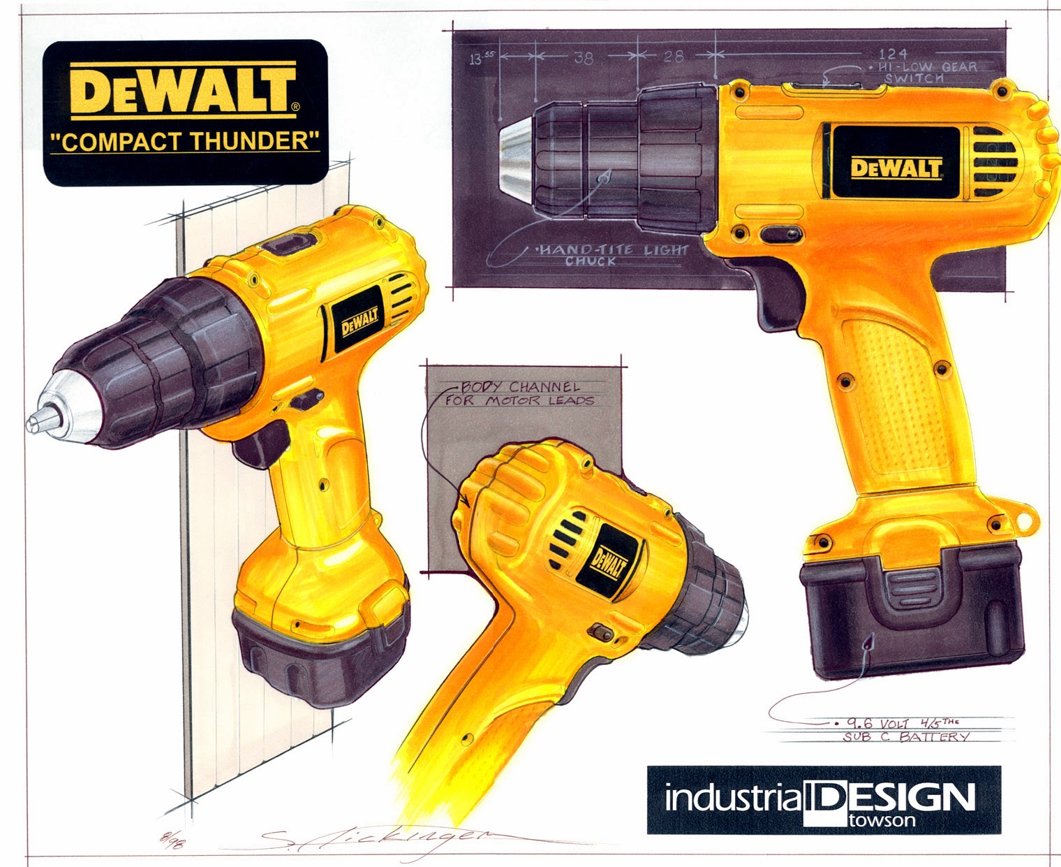
Below are some development sketches of the drill. This drill was designed as an entry level unit for the DeWALT brand and was designed to be rather plain compared to the higher end drills. But even with this design parameter, three distinctive design details emerged by making the housing as compact as possible to compete with the Makita's small design that made it easier to get into tight spots. The first are the two bumps  running longitudinally on the sides of the drill. These are localized bump outs to make room on the inside where screws join the motor to the gearcase. The normal practice was to make the housing a constant  cylinder shape that inclosed everything on the inside with no external details, but the internal screws were the only things needing to go out that wide so I developed the bumps to keep things compact. The other design detail is the channel coming off the back of the handle and running under the main body then up the back. The housing design was so tight to the motor that there was not enough room to run the lead wires to the motor so this channel was designed to carry the wires. A problem some uses have with drills is that their  lower thumb knuckle rubes against the main housing and gets sore, this channel moved the hand away from the housing enough to stop those issues. The final feature is the extension of the housing under the clutch collar. This was done so we could move the handle forward to balance the drill on its battery. This has now become a common theme on many DeWALT and other company drills.


 This next group of sketches shows development of the clutch collar details and bit holder solutions.


This rendering shows the final intended design. Some testing results and project scope changes led to the an additional screw being used to hold the back end of the housings together and the clutch collar was resigned to match an off-the-shelf chuck.

Marker Rendering of the DeWALT Project "Compact Thunder"


Below is pictured the final production unit with its European counterpart in the Elu brand colors. The Elu brand was eventual phased out and replaced with the DeWALT brand name. To see more power tool projects or see the design services I offer clients, visit  my website at Bullseye Design Worx.  You can also click on the labels to the right to search for specific projects or skills.

 Final Production Design - DeWALT 9.6 Cordless Drill


Sunday, February 2, 2014

Ducati SS-T "Design your Dream Ducati" Contest


This is a little personal project I did in 2003 for the "Design your Dream Ducati" Contest.This is an example of Ducati doing "crowd sourcing" before it became hip. Over a 1000 entries were submitted from all over the world at the cost of only two motorcycles. Okay, so on to my entry....

The SST is a Super Sport Touring bike. The idea being that you could ride it at the track by easily removing the side mirrors with integrated turn singles, quickly drop the  clamp-ons below the shock's top clamp and raise the rear set up under the seat. Then you could revert it back and comfortably ride the bike on your favorite set of road twisties for a few hours.


I challenged myself to style the bike in a very clean and graphic manner. I split the windscreen down the middle but ran it clean around the bottom of front fairing giving it a vertical layout . In contrast most sports bikes at this time had a horizontal layout of intakes and headlights. The SST headlights were hidden behind the windscreen to  keep the lines clean. The air intake was put at the very front center of the fairing to grab the air before it was disturbed by running across any body surfaces. The side fairings are kept clean, like the 999, not junked up with a bunch of gratuitous styling elements like most other sportsbikes.


To run the air the from the front intake straight into the airbox I had to change the design of the normal center steering tube. Instead I created two very large being races for the steering to work from and then connected the top and bottom with support framing on the side. This allows the air ducting to run straight through the axes of the steering and into the airbox without any bends. The ducting can be faintly seen through the large steering ring.  Had this been a cruiser or chopper bike I would have put the RPM gauge in the the ring but to keep it and the over lapping speedometer easily visible I placed them in the normal position.


Another difference from most sportsbikes is the shape of the front fairing. In top view you can see that it tappers off to the sides more than most designs to divert air flow around to the sides of the rider. Not all air  goes around but it reduces the amount of air being directed straight up into the rider's chest and head, reducing drag and wind buffeting.


The modeling and render for this project was all done in Alias.

To see more examples of real projects and the design services I offer please visit my website by clicking here, Bullseye Design Worx. To see more computer modeling and renderings click here.